
From Concept to Construction Getting Retention Systems Right
Safe and efficient basement excavations depend on well-designed retention systems. In this article, Madan Kumar Annam, Engineering Director, Keller Asia, highlights the essential “No-Go” rules, design checks, and geotechnical insights that help prevent costly failures and ensure long-term stability in deep urban projects.
Introduction
Basement excavations are often the most complex and risk-laden stages in urban construction projects. As cities grow vertically both above and below ground, the need for safe and efficient deep excavations drawn attention of earth retention systems to the modern geotechnical engineering solutions. These structural walls, often built before excavation begins, form both the permanent basement wall and the primary lateral earth retention system. However, improper design and analysis can lead to catastrophic failures endangering lives, delaying projects, and incurring enormous costs. To ensure robust performance, engineers must adhere to a series of “No-Go” rules and critical checks that should never be bypassed during design phase. This article outlines these essential rules and emphasizes why a well-executed retention system design is not just preferable, but essential for safe basement excavation.
Why retention system design needs special attention
Before delving into the key design rules, it is important to understand why retention systems require an utmost level of care compared to shallow or deep foundations. Basement excavations must temporarily hold back lateral earth pressures from surrounding soil, groundwater, and nearby buildings. When soil is removed during excavation, the horizontal stresses previously sustained by that soil are no longer resisted, leading to a reduction in lateral confinement. As a result, soil relaxes laterally as it adjusts to the new stress boundary, reducing horizontal stresses and potentially initiating lateral deformation or instability. Unloading conditions in Geotechnical Engineering is critical and failures can occur instantaneously with less or no warning signals. The consequences of failure include excessive wall movement, soil collapse, damage to adjacent structures, and even complete excavation retention system failure. An effective design must integrate geotechnical understanding, structural detailing, groundwater modelling, and realistic construction sequences. Ignoring any of these components compromises the safety and serviceability of the retention system.
Understanding of geological conditions for safe excavations
A thorough soil investigation of the project site is fundamental to the success of earth retention systems. For geotechnical engineers, the process begins with smart planning for borehole locations, appropriate depths, and relevant in-situ and lab tests based on expected strata and excavation depth. Careful review of field logs, groundwater conditions, and lab results helps identify critical strata transitions, soft zones, and variability. Engineering analysis should then focus on strength, stiffness, and time-dependent behavior of soils, factoring in construction sequences, dewatering effects, and surcharge loads. Translating this into design parameters requires engineering judgment, especially to distinguish short-term (total stress/undrained) versus long-term (effective stress/drained) conditions for excavation stability, wall deflection, and basal heave. A robust soil model rooted in investigation outcomes, is not just a design input but critical to safety, constructability, and performance of deep excavation projects. Incomplete or misinterpreted investigations often lead to costly redesigns or failures.
Analysis & Design of Retention System: Engineering beyond software
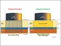
A well-designed retention system starts with a clear understanding of the risks involved. The analysis and design of retention system demands rigorous consideration of soil-structure interaction to accurately capture the complex interplay between earth pressures and structural response. Earth pressures are critically influenced by soil characteristics such as shear strength, stiffness and stress history. The wall's bending moment and deflection profiles, governed by soil stiffness and loading conditions, must be assessed in conjunction with the type and spacing of lateral supports. Sufficient embedment depth ensures global and local stability, especially in cantilever and propped configurations. Analytical methods, ranging from classical limit equilibrium or subgrade modulus method or finite element modelling (Figure 1), must be selected based on the project complexity. Counter checks, including sensitivity analyses and comparison with empirical methods or case histories, are essential to validate design robustness and performance reliability. Designers must also consider nearby structures while performing analysis that could be affected by excavation or wall movements.
Limit equilibrium analyses provide insights for global stability and factor of safety checks but often fails to accurately estimate deformation behavior. Limit equilibrium method in retention wall design assumes linear earth pressure distributions and ignores soil structure interaction, unlike subgrade reaction or finite element methods. Limit equilibrium has limitation of capturing staged construction or stress redistribution, leading to less accurate bending moment and deflection predictions, especially in complex or multi-stage excavation scenarios.
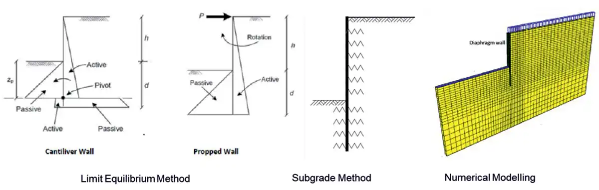 Figure 1: Methods of retention system analysis
Soil–structure interaction methods, such as the subgrade reaction approach or finite element analysis, are preferred for earth retention wall design because they realistically couple wall stiffness with mobilised soil pressures, capture load changes during staged excavation, and account for stress redistribution and time-dependent effects. These capabilities ensure accurate prediction of bending moments, deflections, and support loads in complex retention systems. The reliability of soil structure interaction methods for deep excavation analysis depends on understanding of soil mechanics, accurate characterization of soil behaviour and parameters, and proper modelling of structural properties. Equally important is a clear understanding of the capabilities and limitations of the chosen analytical method and any software used.
In current Indian practices and codes, the design of retaining walls typically adopts a lump-sum factor of safety. The calculations are carried out under the Serviceability Limit State (SLS), with overall safety factors applied to both geotechnical and structural considerations. In contrast, some international codes follow a partial safety factor methodology, where distinct safety factors are assigned to account for different sources of uncertainty, such as soil properties, material strengths, and applied loads. Moreover, international codes explicitly address both Serviceability Limit State (SLS) and Ultimate Limit State (ULS) conditions in embedded retaining wall analysis.
Drained & Undrained behavior: Nicoll highway collapse (Singapore, 2004)
Both drained (effective stress) and undrained (total stress) analyses are vital in retention system design as they capture soil behaviour under different loading and time conditions. Correctly distinguishing between them ensures the accurate modelling of wall pressures, stability, and deformation, supporting safe and economical excavation solutions. Retention system analysis performed using only undrained parameters can create an unsafe environment for workers in excavation pits, especially in stiff to hard clayey soils. Hence, it is suggested to check analysis for drained conditions addressing long-term stability of the wall.
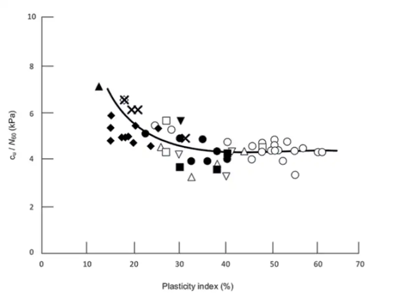 Figure 2: SPT N vs cu correlation (Stroud, 1974)
Clayey soils exhibit complex behavior that changes with time and loading rate. Initially, the low permeability soil responds in an undrained manner, i.e. the pore water pressure has not had time to dissipate under the new loading conditions, and supports some of the load applied to the soil matrix. As the water pressure starts to dissipate over time, the load transfers to the soil itself, effectively reducing its strength with the removal of the pore pressure support. It should also be noted that undrained and drained conditions have no relation to the water table level; drained conditions occur both above and below the water table. In retention system analysis, misapplying soil parameters can lead to unsafe or overly conservative designs. A critical rule is to never use a single set of parameters without distinguishing between short-term (undrained) and long-term (drained) conditions, particularly for low permeability soils. Diaphragm walls, for instance, experience varying construction stages from excavation to service conditions (long-term use of basement). Short-term excavation stability in low permeability soils should be assessed using undrained shear strength (Figure 2), while long-term effects like final design condition , wall creep, base heave require drained parameters (cohesion c′ and friction angle ϕ′, Ref. Figure 3). Accurate modelling of both behaviours, especially in over consolidated clays with fissures or anisotropy, is essential for reliable design. Soft to very soft clays are typically governed by undrained strength and stiffer clays governed by drained strength.
There are several well-documented failures of earth retention systems occurred due to improper consideration of drained vs. undrained conditions during design and construction. Here is a concise summary of a key case study often cited in technical literature. The Nicoll Highway collapse during deep excavation for Singapore’s MRT exposed the dangers of overestimating undrained soil behavior.
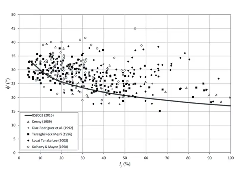 Figure 3: Suggested phi values for Drained Case
Designers used undrained A option along with Mohr Coulomb model, which led to the overestimation of undrained parameters. This led to underestimated basal heave risks and excessive diaphragm wall deflection. As pore pressures rose, the support system failed catastrophically, killing four people and causing widespread disruption. The failure prompted major reforms in excavation design practices. This tragedy underscores the critical need to distinguish between drained and undrained conditions, especially in soft clays during transient construction stages. (Reference: COI Report, Singapore Ministry of Manpower (2005).
No-Go Rule: Never use a single set of soil parameters for low permeability soils without clearly distinguishing between short-term undrained and long-term drained behavior.
Over Dig in basement support system design
Over dig in earth retention systems occurs when excavation exceeds the specified design depth, often due to operator inaccuracy, localised excavations for services/tanks or equipment limitations. This unplanned removal alters soil-structure interaction, potentially increasing the active earth pressure, reduction in passive resistance resulting in excessive wall deflections and ground movements, necessitating careful consideration in design analysis. Ignoring over-excavation in design can lead to unsafe conditions, cost overruns, or failures. Designers must realistically model potential over-dig depths and account for associated risks in serviceability and stability assessments. Integrating over-excavation scenarios ensures robust, constructible solutions that respect ground-structure interaction dynamics.
No-Go Rule: In earth retention works, over dig shall not be permitted under any circumstances. Excavation must strictly follow the approved levels, with constant monitoring and immediate correction of deviations to maintain design intent and ensure structural and geotechnical safety. Never ignore the effect of localized deeper pits or over dig areas in the wall design. It is always suggested to consider a 500mm thick over dig while performing retention system analysis.
Groundwater Table: A critical factor in basement support design
Groundwater conditions play a critical role in the analysis and design of earth retention systems, influencing both stability and serviceability. The presence of groundwater alters effective stresses in the soil, directly affecting deformation behaviour and earth pressure distributions. Elevated water pressures can reduce stability, increase basal heave potential, and cause seepage forces that may lead to piping or internal erosion. If groundwater effects are not adequately considered, the consequences can be severe, ranging from underestimated structural loads and excessive wall deflections to catastrophic failures such as wall collapse or ground loss impacting adjacent structures. Classic case histories, such as those documented in Terzaghi and Peck’s Soil Mechanics in Engineering Practice and CIRIA C760 guidance, highlight numerous excavation failures linked to poor groundwater control or inaccurate hydrogeological modelling. Proper groundwater assessment, incorporating seasonal variations, construction dewatering effects, and transient responses, is therefore fundamental for safe and durable retention system design. Figure 4 illustrates effects of ground water table on earth retention systems.
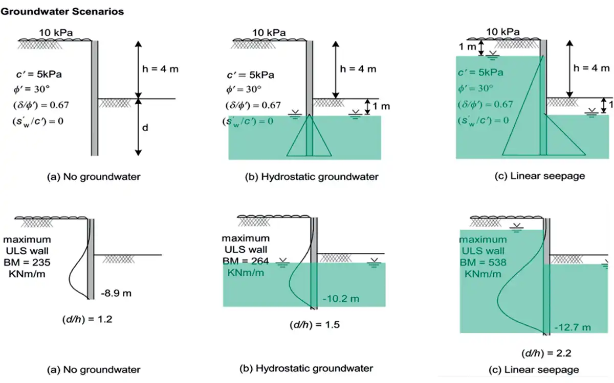 Figure 4: Influence of groundwater on BM and embedment depth
Importance of soil stiffness in the design of earth retention system
In basement excavations, soil stiffness typically expressed as Young’s modulus (E) is a key parameter influencing how earth retention systems behave. Unlike strength parameters, which govern ultimate stability, stiffness controls how much the soil deforms under stress, directly impacting the wall deflections, bending moments, and system performance. For geotechnical engineers, selecting appropriate stiffness values is critical in numerical analysis and finite element models. Soil stiffness varies with type of soils, stress level and strain. Engineers must differentiate between initial (small-strain) stiffness for undisturbed response and reduced stiffness at working strains (typically 0.05%–0.5%) that govern wall behavior. High soil stiffness may underestimate deflections and moments, leading to unsafe designs. Underestimating stiffness may cause overly conservative designs and excessive costs.
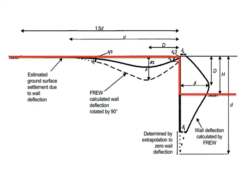 Figure 5: Effects of wall movements (CIRIA 580)
In practice, allowable soil stiffness values range widely; soft clays may have E < 5 MPa, while dense sands can exceed 50 MPa. These must be calibrated using correlations with SPT/N values or advanced testing like triaxial tests in the laboratory, pressure-meter tests or seismic CPT. Soil strain levels are equally crucial: limiting strain ensures serviceability and minimizes structural distress. Excessive wall deflections from overstressed soil can compromise adjacent structures or utilities. Ultimately, soil stiffness isn’t just a number but it governs the balance between strength, movement, and long-term excavation safety. A deflection limit of 0.5% of the excavation depth is commonly adopted in urban areas, with additional settlement restrictions (< 30 mm) for buildings within 5 meters of the excavation. Toe movements of the wall shall be limited to 20 mm. Effects of wall movements are illustrated in Figure 5 and limits of wall movements are presented in Figure 6. The guidelines provided herein are intended for general understanding. The Designer shall exercise professional judgment, duly assess and interpret the actual site conditions, and make design decisions accordingly.
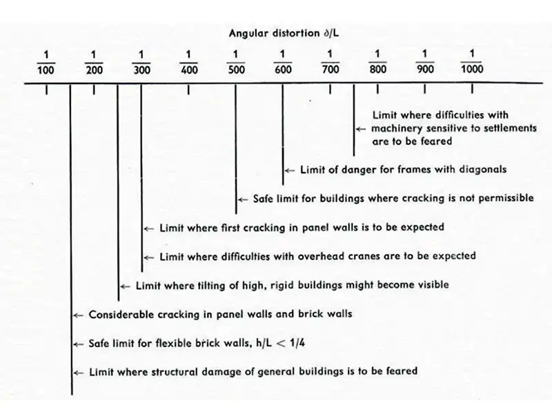 Figure 6: Limits of wall movements (Bjerrum, 1963)
Wall cracking must be carefully controlled, especially for permanent retaining structures. A serviceability crack width limit of 0.3 mm is a general benchmark, though more stringent limits may be applied for water-retaining structures. Anchor forces, strut reactions, bending moments, and axial forces must be extracted from design outputs and verified for structural detailing adequacy. Anchors installed at a steep rake, for example closer to vertical than to horizontal, apply a vertical component of their force to the wall as a vertical load on the wall. This vertical load needs to be assessed against the geotechnical capacity of the wall in permanent contact with the soils.
Surcharge Effects in Earth Retention Design
Surcharge loads are external forces applied behind the retaining wall, typically at the ground surface near excavation which are critical loads in the design of earth retention systems. These loads can be caused from nearby structures, traffic, construction equipment, or stockpiled materials. Surcharge loads increase earth pressures on wall, leading to higher bending moments and greater wall deflections. Failure to correctly account for these loads can result in under-designed systems, excessive wall movement, or even structural failure. Engineers must consider both uniform and point loads to evaluate their influence zones and apply appropriate load distribution models. Importantly, surcharges during temporary construction phase may govern early-stage stability, while permanent loads dictate long-term behavior. Understanding the timing of surcharge, magnitude, and footprint of surcharge loads is key to safe, efficient excavation support.
No-Go Rule: Never finalize retaining wall design without clarity on surcharge magnitude, location, and timing of future loadings; a minimum surcharge of 15 kPa is recommended for analysis.
Why Sensitivity analysis is important for earth retention design
Sensitivity analysis is a vital tool in geotechnical engineering, especially when dealing with earth retention systems for basement excavations. It helps engineers to understand how uncertainties in soil properties, groundwater conditions, and influence over structural assumptions on wall deflections, bending moments, and ground movements. Given the complex interaction between soil and structure, even small deviations in parameters like stiffness or cohesion can significantly affect performance. A geotechnical design engineer must use sensitivity analysis to test the robustness of wall behaviour predictions against varying soil models and load conditions. This process highlights critical design parameters and guides the need for monitoring or design conservatism. Ultimately, sensitivity analysis informs safer and more cost-effective decisions. It helps in optimizing wall geometry, strut levels, and excavation sequences by revealing the range of expected behaviour. It is essential to ensure the design remains stable even under worst-case conditions before the first dig begins, for deep excavations in urban environment.
Conclusion: Avoiding failures through engineering discipline
Getting retention systems right is not only a technical challenge but it is an ethical responsibility of those involved at each stage. Every design choice, from soil investigation to monitoring of wall performance, must reflect a commitment to public safety and professional integrity. Past failures show that when shortcuts replace sound engineering, the cost is measured in lives, delays, and lost trust. By implementing rigorous “No-Go” rules, validating assumptions, and resisting pressures that compromise safety, engineers safeguard both the built environment and the reputation of the foundation engineering profession. In deep excavation design, ethics is not an option, it is the foundation for society.
References:
- Terzaghi, K., Peck, R. B., & Mesri, G. Soil Mechanics in Engineering Practice, Wiley.
- CIRIA C760, Embedded Retaining Walls – Guidance for Economic Design.
- BS EN. 1997, Part 1. 2004. Eurocode 7. Geotechnical design.
- BS 8002. 1994. Code of Practice for earth retaining structures.
- Bjerrum, L. (1963). Allowable settlement of structures. Géotechnique, 13(1), 1–38.
- IGC 2020: Embedded retention wall design practices, consequences and measures, Govind Raj, Madan Kumar Annam.